
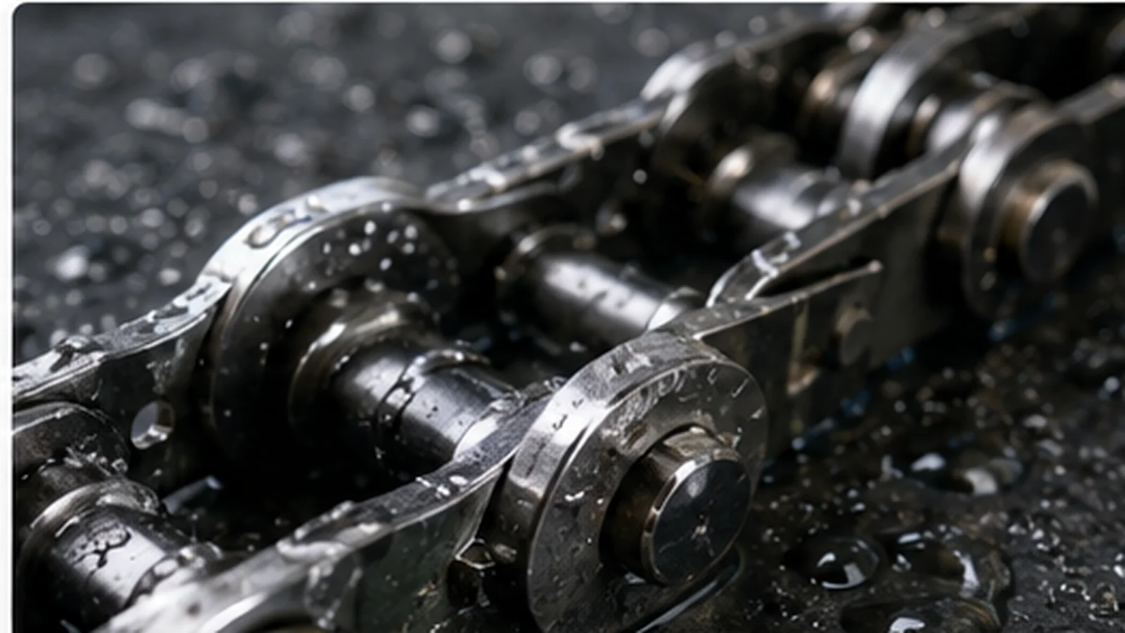
Identify where corrosion is occurring and whether material, chemistry, deposits or galvanic contacts are driving it.
Corrosion diagnosis should distinguish uniform metal loss from crevice attack, deposit-related attack and galvanic effects. The location and morphology matter because changing to a more corrosion-resistant alloy may not correct a crevice or dissimilar-metal design problem.
Identify the physical damage mechanism
Define the scope before measuring: identify where corrosion is occurring and whether material, chemistry, deposits or galvanic contacts are driving it. List which interfaces tied to Wetted and splash-zone locations and Chemical exposure and cleaning will remain in service, and which components can change during the work. That boundary keeps a change to Wetted and splash-zone locations from creating a new mismatch at Dissimilar-metal contacts.
Start by recording wetted and splash-zone locations and chemical exposure and cleaning. Record Wetted and splash-zone locations and Chemical exposure and cleaning while the chain is still in the machine whenever access permits. Use photographs to show orientation, but pair them with dimensions or marked references for Wetted and splash-zone locations and Chemical exposure and cleaning.
If equipment being reviewed for corrosion diagnosis has been repaired previously, assume the current mechanism may differ from an old drawing until wetted and splash-zone locations, chemical exposure and cleaning and the other critical interfaces are checked.
Map where the condition appears
Trace how load enters the chain and leaves it. Relate crevices and deposits to dissimilar-metal contacts and note how both affect load transfer, articulation or fit through the machine path. Relate the observed wear pattern to Crevices and deposits and Dissimilar-metal contacts so the measurement has a mechanical explanation.
Map the working run, return run, drive, take-up and guide locations, then mark where Crevices and deposits enters the load path. Mark where crevices and deposits changes, where wear is concentrated and where a flight, rake or attachment transfers load. This map helps explain why two chains with similar listed dimensions can behave differently around Dissimilar-metal contacts.
On paired-strand equipment, compare both sides at matched stations and note any difference in Wetted and splash-zone locations or Dissimilar-metal contacts. Left-to-right differences can expose alignment, guide or load-sharing problems that are easy to miss when the corrosion diagnosis issue is evaluated one strand at a time.
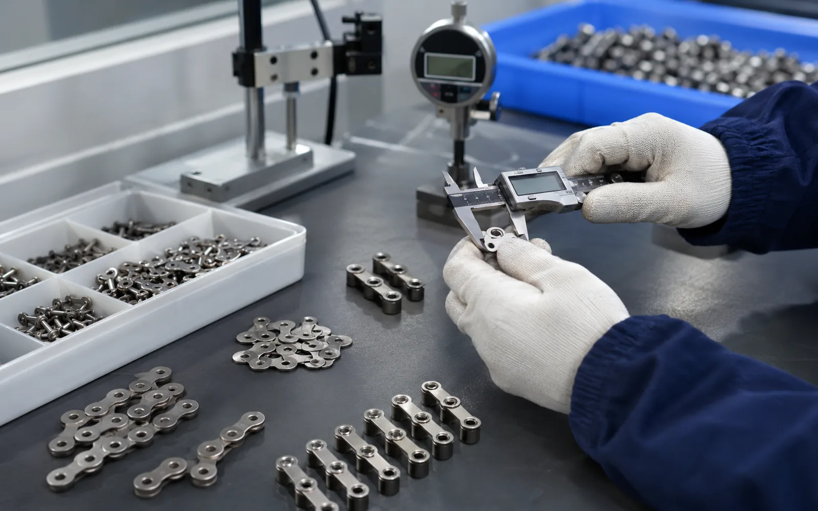
Collect comparison measurements
Build one field-data sheet with separate rows for wetted and splash-zone locations, chemical exposure and cleaning, crevices and deposits, dissimilar-metal contacts and surface loss at pins/plates/attachments. For values related to Wetted and splash-zone locations, Chemical exposure and cleaning or Crevices and deposits, state the measurement reference and whether it came from the installed chain, a removed sample or an approved drawing.
If wear affects Chemical exposure and cleaning or Crevices and deposits, repeat dimensions at several positions and use a longer multi-pitch span for chain length whenever practical. One joint can be damaged locally; during the review, the multi-pitch value should be kept separate from local joint-wear measurements.
Before adjustment or disassembly, capture take-up position, strand timing and visible contact around Dissimilar-metal contacts. Adjusting the mechanism first can erase evidence needed to interpret Surface loss at pins/plates/attachments.
| Field item | What to capture | How it is used |
|---|---|---|
| Wetted and splash-zone locations | Dimension or condition with reference points | Primary geometry or condition check |
| Chemical exposure and cleaning | Repeat at more than one location when worn | Cross-check configuration and wear |
| Crevices and deposits | Photograph and measure the mating interface | Confirm load transfer or attachment fit |
| Dissimilar-metal contacts | Record condition, alignment and whether it stays | Independent machine-interface check |
| Surface loss at pins/plates/attachments | Describe environment, history or trend | Interpret duty and maintenance risk |
Check interacting components
Candidate decisions should now be screened against the fixed interfaces. If wetted and splash-zone locations differs, decide whether the difference is wear, measurement uncertainty or a true configuration change. If a proposal changes Wetted and splash-zone locations, Chemical exposure and cleaning or Crevices and deposits, identify which mating component will remain in service and verify that the change is deliberate.
Use dissimilar-metal contacts as an independent cross-check. A chain can match the listed dimensions yet still seat incorrectly if Dissimilar-metal contacts is different, worn or misaligned. Use Dissimilar-metal contacts as an independent fit check rather than relying on a visual match alone.
Any deliberate change to Wetted and splash-zone locations or Dissimilar-metal contacts should be shown explicitly on the drawing or quotation. The purchaser should be able to see what changes at Wetted and splash-zone locations or Dissimilar-metal contacts and why.
Keep wetted and splash-zone locations and the mating geometry visible in every comparison.
Use surface loss at pins/plates/attachments to distinguish a configuration choice from a wear or maintenance problem.
Define how dissimilar-metal contacts and crevices and deposits will be checked before installation.
Test the most likely causes
Service history helps interpret the measurements. For Surface loss at pins/plates/attachments, note relevant changes in process load, solids, cleaning, blockage events, repairs or alignment, and record whether the observed condition is stable or progressing. A time trend helps distinguish an old condition at Surface loss at pins/plates/attachments from an active failure mechanism.
Inspect adjacent sprocket teeth, guides, take-up hardware, attachments and fasteners while checking Dissimilar-metal contacts. During corrosion diagnosis, the chain can record a problem created elsewhere in the mechanism; replacing it without correcting that cause can reproduce the same wear pattern.
Compare the loaded and return runs at equivalent stations, especially where Crevices and deposits transfers load. Differences can indicate whether the process load or a stationary guide is the dominant source of stress or wear.
Choose a corrective action
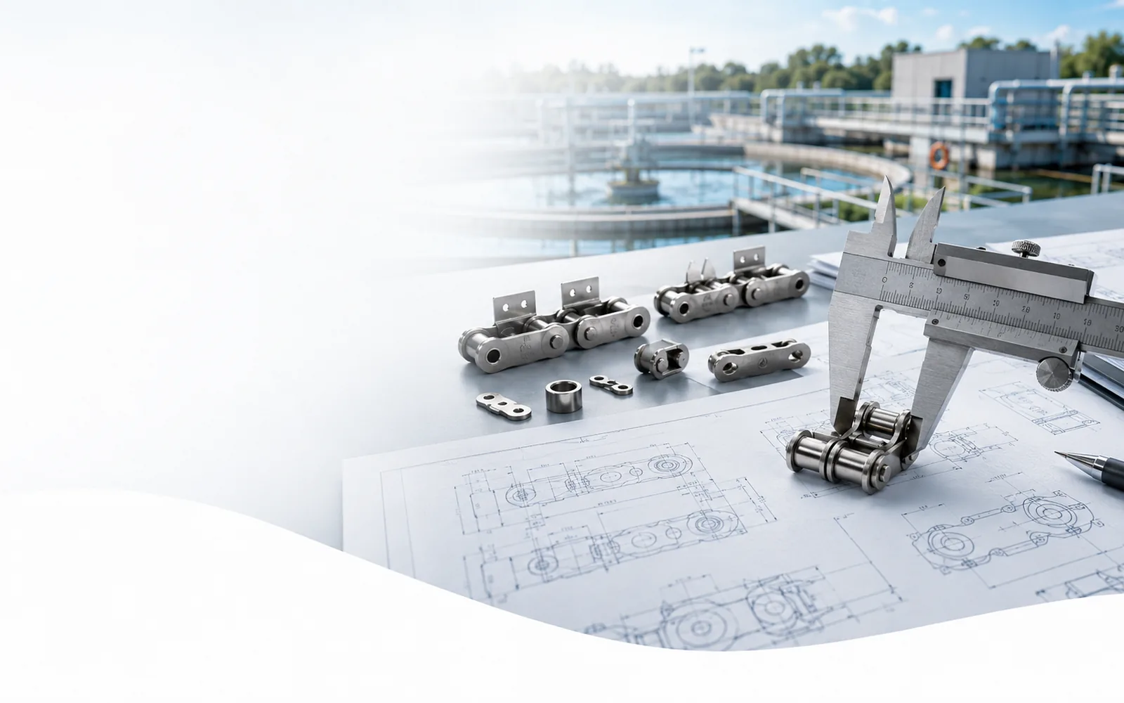
Turn the accepted decision into an RFQ that names the controlling dimensions and interfaces. Include the measured chain geometry, attachment or joining details, mating sprocket and guide information, operating conditions, total length or pitches, number of strands and required quantity. State total chain length or pitches, number of strands, joining parts, attachments and quantity.
State required material, process and inspection documents before quotation so the manufacturing and acceptance scope is clear. early definition keeps the manufacturing route, acceptance checks and commercial minimums aligned with the same scope.
When any mating interface remains uncertain, attach a marked sketch and photographs that identify the reference points. In an RFQ for corrosion diagnosis, the goal is not length; it is enough unambiguous information that different suppliers would be quoting the same geometry and scope.
- Model, drawing or sample identification
- Wetted and splash-zone locations
- Chemical exposure and cleaning
- Crevices and deposits
- Dissimilar-metal contacts
- Surface loss at pins/plates/attachments
- Total chain length or pitches, strands, joining parts and quantity
- Required material/process and inspection documents
For corrosion diagnosis measurements, use the replacement measurement guide. When the uncertainty is the chain family rather than the field dimension, compare the wastewater chain product pages.
Record the repaired baseline
After installation or corrective work, record a new baseline for wetted and splash-zone locations, chemical exposure and cleaning and dissimilar-metal contacts. Add take-up position, attachment timing and representative photographs. These references make the next inspection a comparison rather than another identification exercise.
After diagnose work for corrosion diagnosis, move the mechanism through a complete cycle when safe and permitted. Check tight spots, tracking changes, guide contact and attachment interference at turns and sprockets, not only in an easy straight section.
Plan the first follow-up inspection around the wear, alignment or fit condition most likely to change after commissioning. A short early check can reveal installation settling or an unresolved system issue before it develops into substantial chain or sprocket damage.
Watch for recurrence
A common mistake is to let one convenient number dominate the decision. Compare the primary measurement with mating interfaces, wear pattern and machine condition before accepting a replacement. This avoids false equivalents that fit a table but not the machine.
Do not treat every visible surface change as a material problem. Alignment, abrasive solids, trapped debris, seized articulation and sprocket wear can produce symptoms that look like a chain-material problem until the load path relevant to corrosion diagnosis is inspected.
A practical acceptance test is straightforward: another engineer or maintenance technician should be able to repeat the checks for Wetted and splash-zone locations, Chemical exposure and cleaning and Dissimilar-metal contacts from the record alone.
Records to retain after commissioning
Record the accepted value or condition for wetted and splash-zone locations with a reference that can be repeated.
Keep a photograph or drawing detail showing how crevices and deposits relates to the installed mechanism.
Note the service condition or trend for surface loss at pins/plates/attachments so the next inspection has context.
Store the approved drawing revision, purchase line, joining method and commissioning notes together. If a field adjustment was necessary, record it rather than allowing the machine to drift away from the drawing without explanation. That small discipline makes later diagnose decisions faster and reduces uncertainty in repeat orders.
Field observations that change the decision
Mark travel direction, drive and take-up locations, and the station where crevices and deposits transfers load. Number the inspection points so photographs and dimensions refer to the same physical locations.
For wetted and splash-zone locations and chemical exposure and cleaning, record exactly where the measurement starts and ends. Repeat worn features away from the most damaged location before an agreed nominal value is placed on a drawing.
If dissimilar-metal contacts remains in service, its condition is part of the replacement specification. If it is renewed, state the new mating geometry so the chain and component can be checked as one interface.
| Record | Minimum useful detail | Reason |
|---|---|---|
| Machine map | Working/return runs, drive, take-up, guides and process-element locations | Keeps chain measurements connected to the mechanism. |
| Wetted and splash-zone locations | Measured value, reference points, location and whether the part is worn | Separates field condition from the intended nominal geometry. |
| Crevices and deposits | Drawing/photo of attachment or process-element connection and load direction | Confirms how the process load enters the chain. |
| Dissimilar-metal contacts | Condition, alignment, dimensions and whether it will remain in service | Provides an independent fit and engagement check. |
| Surface loss at pins/plates/attachments | Specific environment, event history and trend rather than a generic duty label | Helps interpret why wear or damage developed. |
Operating information about surface loss at pins/plates/attachments should be specific enough to change an engineering decision. State where the chain is submerged, what solids or debris are present, whether chemical cleaning occurs, and whether jams, shock events or restricted maintenance access influence the duty. Broad labels such as “wastewater service” are useful context but do not replace these machine details.
During quotation review, compare the same fields across proposals: wetted and splash-zone locations, chemical exposure and cleaning, crevices and deposits, dissimilar-metal contacts, material/process requirements, joining construction, inspection documents and commercial quantity. If one proposal intentionally changes a fixed interface, that change should be visible on the drawing or quotation rather than hidden inside a similar model description.
At commissioning, record what actually went into the machine. Keep the purchase drawing, final chain length, joining parts, take-up setting and representative photographs together. For later diagnose work, that baseline lets the maintenance team measure change instead of rebuilding the specification from a worn component.
For corrosion diagnosis, a different technician should be able to revisit wetted and splash-zone locations, crevices and deposits and the same inspection locations at the next shutdown. Consistent references are what turn one inspection into a useful condition trend.
Turn observations into a repeatable check
Before approving a replacement, adjustment or quotation related to corrosion mechanisms in wastewater chains, tie every important observation to a physical reference point. The purpose is not to collect more data than necessary; it is to make the critical geometry, condition and operating evidence repeatable by another engineer or maintenance technician.
| Check | What to record |
|---|---|
| Wetted and splash-zone locations | Record a specific value or condition, the reference used, and enough context for a second technician to repeat the check. |
| Chemical exposure and cleaning | Record location, severity, operating condition and recent process or maintenance changes so the observation can be interpreted in context. |
| Crevices and deposits | Record a specific value or condition, the reference used, and enough context for a second technician to repeat the check. |
| Dissimilar-metal contacts | Record a specific value or condition, the reference used, and enough context for a second technician to repeat the check. |
| Surface loss at pins/plates/attachments | Photograph the interface, measure its geometry or spacing, and identify the retained mating part and direction of load transfer. |
Keep the marked drawing, photographs and measured values together. If a dimension is taken from a worn component, label it as a field condition rather than silently treating it as the new nominal value. This distinction is especially important when a supplier must reproduce an interface that remains in the machine.
Frequently asked questions
What is the first check for corrosion mechanisms in wastewater chains?
Start with wetted and splash-zone locations and the fixed machine interfaces. Then compare chemical exposure and cleaning, crevices and deposits and the mating sprocket/guide condition.
Can the model number be used without field checks?
For a controlled repeat order related to corrosion diagnosis, the model can be a starting point. On old, repaired or modified equipment, verify wetted and splash-zone locations, chemical exposure and cleaning and the interfaces that must remain in service.
How should a worn sample be measured?
For corrosion diagnosis, use a multi-pitch measurement for accumulated length, repeat chemical exposure and cleaning and other local dimensions at several positions, and keep worn values separate from the agreed nominal drawing.
What photographs are most useful?
Photograph the chain seated on the sprocket or interface associated with dissimilar-metal contacts, plus a representative crevices and deposits location, the take-up, guide contact and any localized damage. Add a scale reference where dimensions are not obvious.
What belongs in the RFQ?
Include the chain/model or sample, wetted and splash-zone locations, chemical exposure and cleaning, crevices and deposits, dissimilar-metal contacts, operating conditions, total length/strands and quantity.
When should sprockets be included in the replacement scope?
For corrosion diagnosis, evaluate sprockets whenever dissimilar-metal contacts, tooth wear, alignment or chain elongation suggests the old tooth profile may not seat correctly with the new chain. Base the decision on condition, not an automatic rule.
For corrosion diagnosis, send the chain or drawing, wetted and splash-zone locations, crevices and deposits, sprocket/interface details, machine duty and quantity. The RFQ can then be reviewed against the actual wastewater mechanism.