
Start with the mechanism, then select the chain
Wastewater chains work inside complete machines: clarifiers, sludge collectors, grit handling systems and screening equipment. Each mechanism changes the load path, attachment geometry, guide arrangement and maintenance access, so application context should be reviewed before a replacement is treated as a direct model substitution.

Rectangular Clarifier Chains
Paired chain-and-flight circuits, alignment and take-up.
View application →
Sludge Collector Chains
Wet solids, cyclic loading, flights and maintenance.
View application →
Grit Collector Chains
Abrasive solids, guide wear and articulation.
View application →
Bar Screen Chains
Debris loads, rake attachments and tracking.
View application →Map the entire chain circuit before changing one component
Draw the working and return runs, direction of travel, drive and take-up sprockets, guide locations and the points where flights or rakes transfer load. On paired systems, add strand spacing and attachment timing so the two chains can be compared as one mechanism.
For replacement work, photographs of the chain seated on the sprocket, the take-up position and a typical attachment station are especially useful. They show relationships that are easy to miss when the chain is measured after removal.

Application variables that change the replacement decision
| Area | What to record | Why it matters |
|---|---|---|
| Chain path | Submerged sections, return supports, guide material, elevation changes | Controls support, articulation and areas where solids can accumulate. |
| Process load | Sludge, grit, debris, rake or flight duty, intermittent shock | Helps separate normal conveying load from abnormal events or binding. |
| Attachments | Style, spacing, hole pattern, offset and flight connection | Determines whether a base chain can accept the installed process element. |
| Sprockets | Tooth count, face width, bore/shaft, alignment and wear | Directly controls chain seating and articulation at every revolution. |
| Maintenance | Take-up travel, access, cleaning practice and shutdown window | Affects inspection strategy and how much work can be completed in one outage. |
A chain with the correct pitch can still be wrong if its width, attachment geometry or sprocket interface does not match the machine. Treat pitch as the first filter, not the final answer.
Use application data to narrow the product family
Begin with the mechanism and fixed interfaces. Next compare chain geometry and construction, then review material and wear conditions. Only after those checks should a specific model be treated as a preferred candidate.
If the equipment has been modified in service, record the installed dimensions rather than assuming the original design remains unchanged. This is particularly important when sprockets, guides, flights or take-up components have been repaired independently.
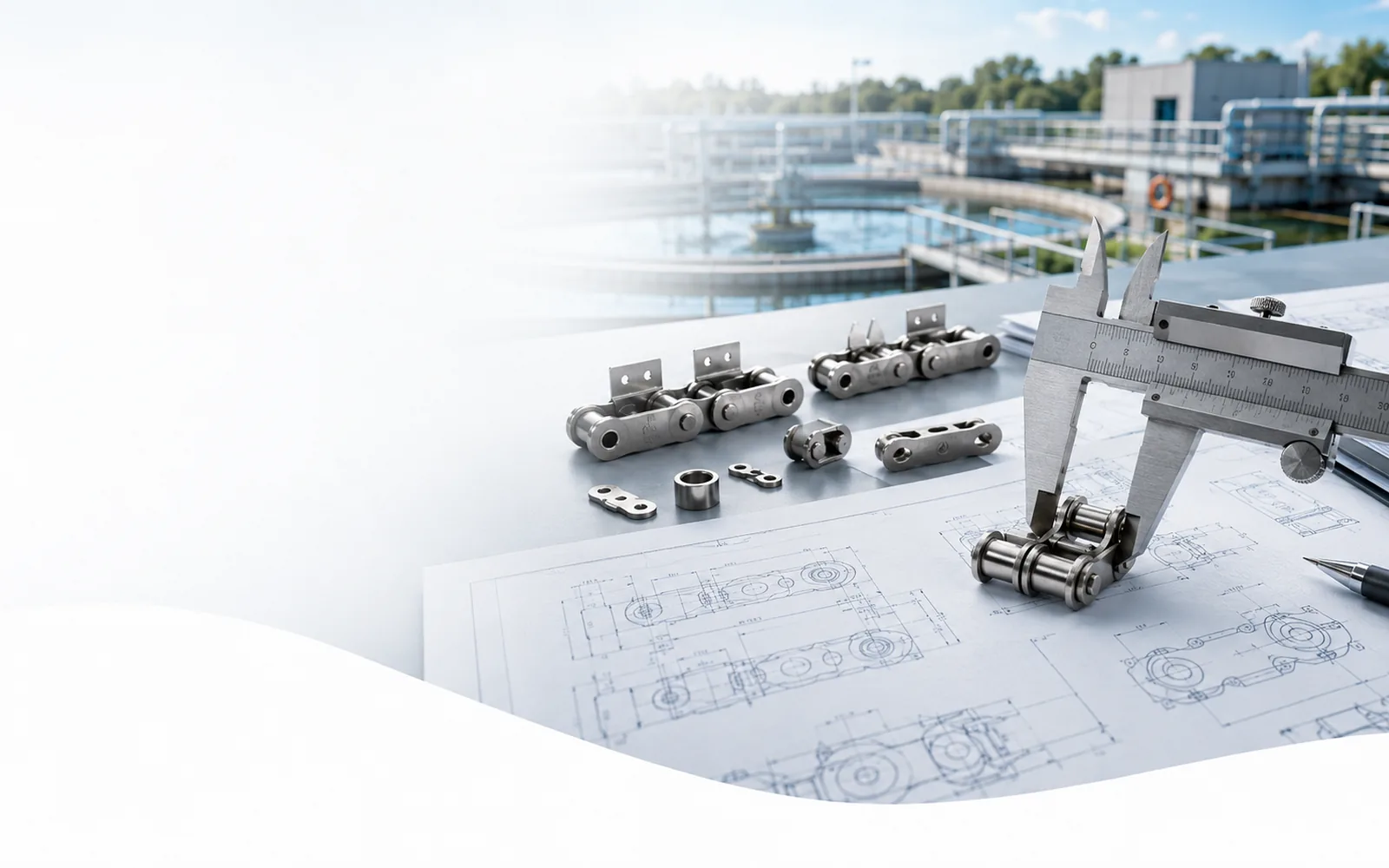
Information that lets the application and product be checked together
- Equipment type and process duty
- Chain model or marked sample
- Pitch, width, pin/barrel dimensions and overall pin length
- Attachment drawing and interval
- Sprocket tooth count, face width and wear condition
- Total chain length, number of strands and quantity
For projects that combine several chains, identify each model by equipment and strand so dimensions do not get mixed between clarifier trains or process areas. Use the engineering section for measurement and attachment guidance.
Give the supplier the data that changes the application decision
Send a marked drawing or sample measurements together with photographs of the chain seated on the sprocket, a typical attachment, the take-up and any concentrated guide wear. Identify which mating parts will remain in service.
Provide the general chain path, shaft centers, proposed sprockets, strand spacing, flight or rake geometry, operating cycle and process load. State where the chain is submerged and where maintenance access is limited.
Add the observed symptom—uneven elongation, seized joints, tooth hooking, broken attachments or repeated rubbing—and show where it occurs in the circuit. A failure location is often more useful than a generic statement that the chain is worn.
When several chains are being replaced in one treatment plant, label each equipment train and strand separately. Do not merge measurements from different collectors simply because the model name looks similar. A project can still be quoted commercially as one package while the engineering data remains traceable to the correct machine.
Where drawings and field measurements disagree, identify the controlling interface before quotation. The correct answer may be the original drawing, the installed machine or a deliberate redesign, but the difference should be visible and agreed rather than silently averaged.
Compare the mechanism before comparing chain models
Clarifiers, sludge collectors, grit collectors and bar screens all use chain to move a process element, but the mechanical risks are not the same. The application review should identify the load-transfer point, the stationary surfaces that guide the chain, the sprockets that index it and the maintenance conditions that determine what can actually be inspected or adjusted.
Prioritize paired-strand synchronization, flight squareness, shaft/sprocket alignment and the available take-up range. A phase difference between strands can overload attachments even when each chain is dimensionally correct.
Combine elongation and take-up trends with wet-solids buildup, guide contact and attachment condition. Deposits can hide rubbing or loose hardware, so representative areas should be cleaned before assessment.
Map where abrasive solids accumulate and where sliding or articulation occurs. Concentrated grit at a guide or pin/barrel interface can dominate wear even when the rest of the circuit looks serviceable.
Review rake attachment geometry, debris pickup/discharge and known jam events. Irregular debris creates local peak loads that are not represented by average chain tension alone.
| Decision point | Field evidence | Use in selection |
|---|---|---|
| Geometry | Multi-pitch length, working width, pin/barrel/roller dimensions, attachment envelope | Eliminates candidates that cannot fit the installed path. |
| Mating parts | Sprocket tooth count/face, shaft alignment, guide clearance and take-up position | Confirms engagement, tracking and whether existing components can remain. |
| Process duty | Submergence, solids/grit/debris, cleaning chemistry, cycle pattern and blockage history | Identifies corrosion, abrasion, articulation or shock mechanisms that need attention. |
| Maintenance | Access, shutdown window, joining method and spare strategy | Determines whether the proposed configuration can be installed and serviced realistically. |
Carry application assumptions into the first operating baseline
After the selected chain is installed, record the take-up position, representative multi-pitch length, attachment timing and visible sprocket/guide condition. On paired collectors, use the same station references on both strands so later inspections can detect loss of synchronization rather than only total wear.
Run or rotate the mechanism through the complete permitted path before treating a straight-run fit check as sufficient. Watch attachment clearance at turns, transitions and sprockets; confirm that flights or rakes remain aligned where process load is transferred.
Use the application page that matches the actual equipment, then send the model or sample information, marked dimensions, sprocket data, duty and quantity through the RFQ section below. That keeps the commercial enquiry tied to the same mechanism used for technical selection.