
What the equipment requires from the chain
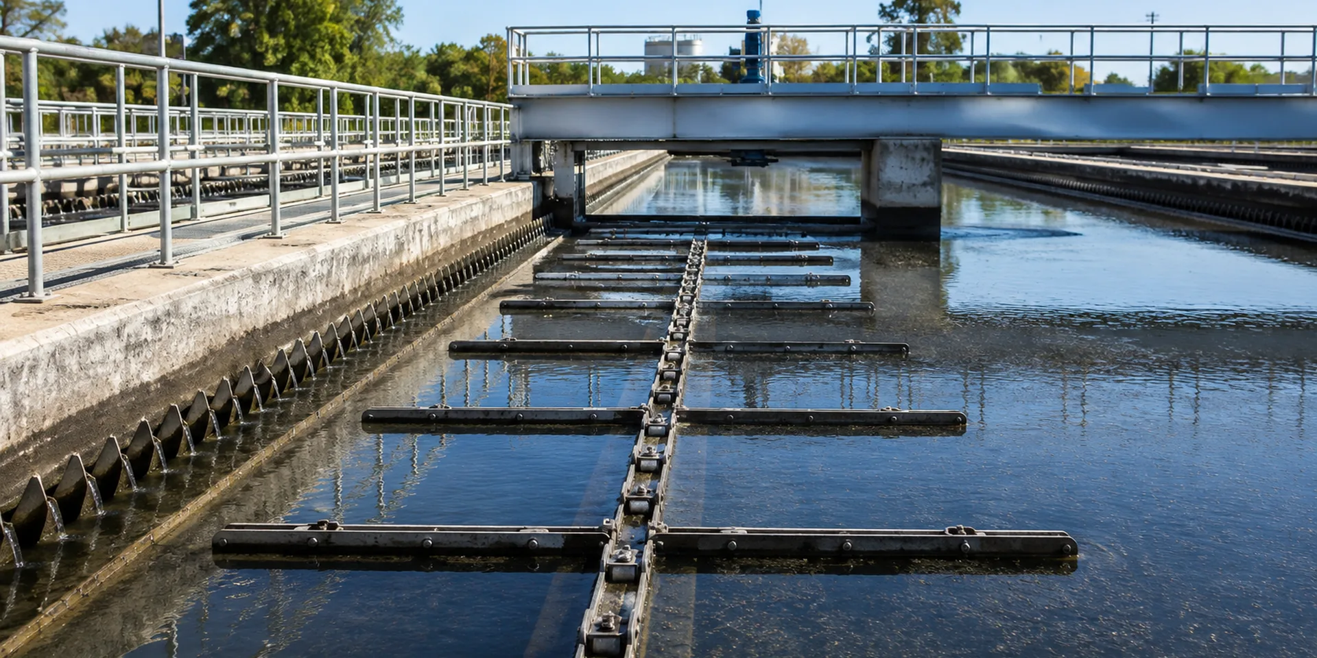
Sludge collector chains work in wet solids, cyclic loading and restricted maintenance spaces. Inspection should connect pitch growth and attachment condition with guide wear, strand balance and sprocket condition.
Review multi-pitch elongation trend and attachment and flight condition before treating a model number as a direct replacement.
Check paired-strand balance together with guide wear and debris buildup so the chain is evaluated inside the actual mechanism.
Use sprocket tooth seating to decide what must be inspected or confirmed before production.
Understand wet solids handling and repeated collector cycles
The chain carries tension, but the surrounding mechanism determines how that tension becomes useful work. For sludge collector chains, the critical relationships include multi-pitch elongation trend, attachment and flight condition and paired-strand balance. A change in one area can shift load into the guides, attachments or sprocket teeth.
Before a replacement is released, record guide wear and debris buildup and sprocket tooth seating. These observations help distinguish a dimensional mismatch from a maintenance or alignment problem.

Measurements and observations to capture
| Check | Recommended field record |
|---|---|
| Multi-Pitch Elongation Trend | Measure or describe the installed condition. |
| Attachment And Flight Condition | Record the operating condition and visible wear. |
| Paired-Strand Balance | Confirm the mating component or interface. |
| Guide Wear And Debris Buildup | Mark the value on the drawing or field sketch. |
| Sprocket Tooth Seating | State whether the item will remain or be replaced. |
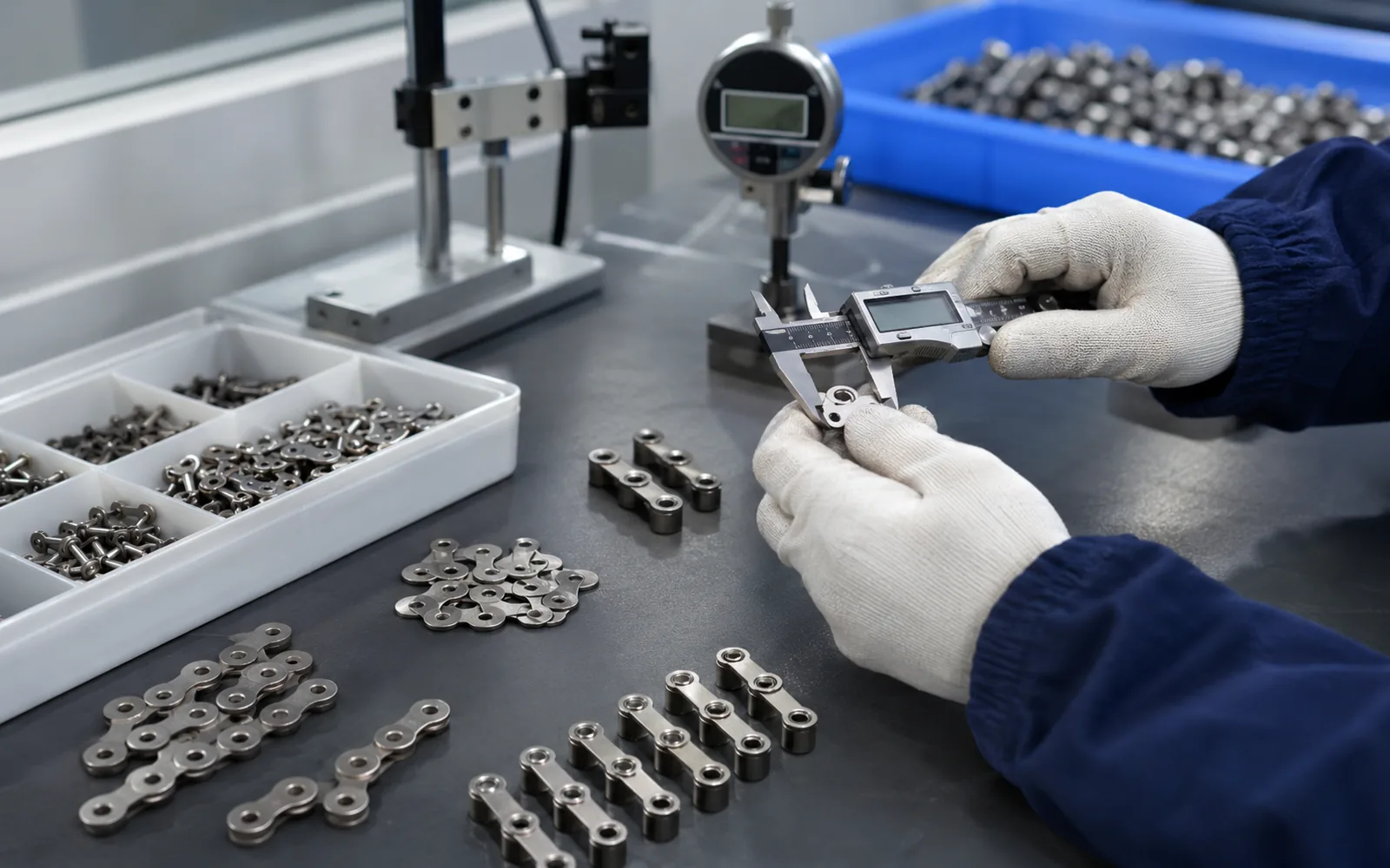
For sludge collector chains, take measurements at more than one position when wear is visible. Label values taken from the installed part separately from values copied from an old drawing so the engineering team can see which dimensions still need agreement.
Check the chain together with sprockets, guides and process elements
Photograph the chain while it is still seated in the machine. Include the sprocket tooth profile, guide contact areas and one representative attachment station. For paired systems, compare both strands and note whether flights remain square through the circuit.
If paired-strand balance or guide wear and debris buildup will be retained, treat it as a fixed interface. If it will be replaced, the chain and mating part can be evaluated as a matched set rather than forcing the new chain to follow worn geometry.
Questions to answer before selecting a model
- Is multi-pitch elongation trend measured at several locations or only copied from an old record?
- Does attachment and flight condition match the installed process element and both strands where applicable?
- Will paired-strand balance remain in service, and is its condition acceptable?
- Is guide wear and debris buildup free from interference, one-sided wear or unexpected field changes?
- How does sprocket tooth seating affect inspection, material choice or shutdown planning?
- Are chain length, strand count, joining method and required quantity stated clearly?
Pitch narrows the search, but working width, bearing geometry, attachments and sprocket seating determine whether the chain can run through the machine without interference.
Separate wet-solids loading from alignment and articulation wear
Sludge collectors combine submerged service, settled solids and repeated flight loading. Deposits can hide early rubbing or loose hardware, so cleaning representative joints and guide areas is part of a meaningful inspection rather than a cosmetic step.
| Review point | What to check | Why it matters |
|---|---|---|
| Articulation | Clean and flex representative joints; record seized or unusually stiff positions. | Restricted articulation raises chordal and tooth-entry loads and can imitate a material-strength problem. |
| Flight hardware | Check fastener security, hole elongation, bracket distortion and strand-to-strand timing. | Loose or distorted attachments change how sludge drag enters the chain. |
| Guide contact | Map polished or worn guide zones on working and return runs. | Localized contact helps distinguish alignment error from uniform abrasive wear. |
| Sludge/debris load | Note settled solids, cleaning practice and blockage history around the collector path. | Process buildup can create peak loads that are not visible in nominal conveyor calculations. |
Link the engineering decision to commissioning and maintenance
Do not interpret a dirty or corroded surface as proof that the chain material is wrong. First determine whether the damage follows a guide, a blocked area, a seized joint or an attachment load path; the corrective action depends on that pattern.
Trend multi-pitch length together with take-up position and sprocket condition. If the take-up moves rapidly while only one strand shows concentrated guide wear, investigate alignment and load sharing before ordering a heavier chain.
Tie photographs, field measurements and the final drawing to the same equipment or line item. If a value is worn, estimated or still uncertain, mark the uncertainty clearly on the RFQ or drawing before quotation.
Plan checks that can be repeated after installation
For sludge collector chains, record a baseline multi-pitch measurement and take-up position after installation when practical. Add photographs of the attachment and sprocket condition. A repeatable baseline makes future wear trends easier to interpret.
If an installation adjustment changes an attachment, guide or take-up setting, update the equipment record so the next replacement starts from the configuration that is actually running.
Prepare a quotation package around the machine interface
Send the model or sample, a dimensioned sketch, photographs of the chain in the mechanism, sprocket data, application conditions and the required length or quantity. State which mating parts will remain and which can change.
For related model options, browse the wastewater chain product families. If the chain cannot be identified confidently, use the replacement measurement workflow before requesting an equivalent.
Collector-floor clearance and deposit loading
Sludge collectors operate close to the tank floor, so chain selection cannot be separated from flight clearance, settled-solids loading and the condition of return supports. Record the minimum flight-to-floor clearance, locations where solids accumulate and whether the removed chain shows localized wear near those zones. A chain that fits the sprocket but changes attachment height or flight attitude can increase drag substantially.
For a replacement project, include photographs of the drive, take-up, return track and one typical flight connection. Note whether shutdown inspection reveals grit embedded at pins or bearing surfaces, polished guide contact or unequal wear between strands. These observations help distinguish a geometry problem from a material or maintenance problem and give the quotation a clearer definition of the operating duty.